« Archives in December, 2013

One more thing re Weight and Balance

1.0 hours.

I almost forgot.   Yesterday I had to lift the tail to make the plane level again, because I forgot to do a couple of crucial measurements.

Without going into great detail on what weight and balance is and how it’s calculated, just understand that all the center-of-gravity or CG calculations are done based on distance from a fixed point in space, called the datum.  Yeah, it’s the singular form of ‘data’ but you knew that.  Moving on.

The datum for the RV7 is established by the designers at 70.00 inches forward of the leading edge of the wing in level attitude.    Distance from the datum is measured at a couple of places, like the center of the main wheels and tail wheel, and other distances are given, like the passenger position and the baggage position.   Those distances are called “arms” and when multiplied by the weights at the wheels gives “moments” in inch pounds.   This lets you do all sorts of interesting things like figure out how much that diet of cheeseburgers and Budweiser  is preventing you from taking off with more than half-tanks of fuel and a pair of silk briefs in a tube for baggage.

To get these measurements, I took a couple of plumb bobs and hung them over the leading edge of each wing near the wheel centers.   That distance +70 was the arm at the main gear.   Another couple of plumb bobs got me what I needed at the tailwheel.

So now I have all the relevant weight and measurements to work up my weight and balance sheets.

Idle fixed.

5.5 hours.


I don’t have time for a lot of jibber-jabber, so I’ll make this short and sweet:

I installed the new idle linkage bearing and spent a bit of time dialing in the idle.   I got it to idle smoothly at 750 RPM with a solid transition to power on throttle advance.   CHT’s sitting there uncowled don’t get past 245, which is good.   We had a really strong wind today, so it was a good day for engine testing, but a crap day for flying.  Nobody was out there, so I was left to my own devices.  The idle fix took about two hours, so then I went for a drive.   I taxied down to the west end of the runway, then came back.   20+ knot winds variable from 070 to 085 make for some fast footwork on the pedals.

After that was done, I set about making the fire extinguisher mount.   I ended up putting it on the fuel pump cover, in easy reach of both pilot and copilot.  Of course, if the fuel pump’s on fire, getting the the extinguisher is going to be interesting.   I had to reinforce the fuel pump cover with some .032 so the bracket could be safely bolted on, but it seems to work.


The Weight of the World

6 hours.

I got a bit of a late start, since I spent about an hour trying to source a Heim joint of the correct size from a local speed shop rather than waiting for ACS to ship me one.  In the end, I was unsuccessful, so I made my ACS order and headed out.   Once I got to Oxnard, I stopped in at Aswell Trophy on Oxnard Blvd and they engraved my data plate while I waited.   Took about 15 minutes.

IMG_1718

This was the first task of the day.   After that, I went on to the process of weighing the airplane.   The scales are for weighing race cars, so there are 4 inputs, but I was only using 3.  The measuring unit connects to big metal pads that the airplane sits on and totals up the readings from all of them.

IMG_1721

Some clever person at EAA723 built these ramps to roll the wheels up onto the scales, which was awesome.   I couldn’t find a soul around when I was doing this and I couldn’t get enough oomph behind the airplane to roll it up on there by myself.  I didn’t want to get too big of a running start at it because I didn’t want the wheels to overrun the chocks at the end of the ramps.   So I turned the ramps around backwards, wrapped a strap around my tailwheel spring, hooked that up to my truck hitch, and towed the airplane, very slowly, into position.  The reason you see the wheel pant sitting on the wheel is because I wanted to account for the fairing weight and I haven’t actually finished the fairings yet.   The clecos will probably equal the fastening hardware, and if not, they’re well within the margin of error on the scales.

IMG_1720

The airplane needs to be weighed in level flight attitude.   This means the tail has to go up.   I used my smart levels on the longerons and cranked up the tail on Ron’s old lift with the tailwheel on the 3rd scale.   With all that stuff in place, I came up with these numbers:

  • Left Wheel:     524lbs
  • Right Wheel:   523lbs
  • Tail Wheel       67lbs
  • Total:              1114lbs

So not too bad.   The reference example they give in the construction manual totals in at 1111, so I’m 3lbs more portly than the book.


Zero Sum

6 hours.

I spent a whole lot of yesterday doing various things, which is the surest way to feel like I got nothing done.   I had two goals: Fix the idle stumble and run down that AP engage joystick wire issue.

The first part was almost easy.   I set the mag timing to 25 degrees per the engine data plate.  I’m getting to be an old hand at setting mag timing.  I got them both firing in sync, then made the idle richer by a couple of flats of the adjustment linkage, per the AFP manual.  Sure enough, that cured the off-idle stumble and my CHT’s and EGTs dropped noticeably.  But there was still a rough idle, so more adjustment needed to happen.

The manual says that adjusting the idle is done with the engine running.  The problem with that is twofold: One, working near a spinning prop scares the crap out of me.  I haven’t had the training to do so safely.  Two, because of the orientation of the throttle body, the idle linkage is on top, between the throttle body and the engine case, and the only way to get at it is by reaching past hot exhaust pipes.  Even if I did have the stones to crawl under there with the prop spinning, I can just see burning my forearm on the #1 pipe and yanking it back into the arc of the prop.  No thanks.  I did my idle adjustments with the engine off.

With Mike as the casual observer, it appeared that my idle was too rich, because there was a bit of smoke coming from the pipes when I was idling and the idle was definitely a bit rough.   This is caused by multiple symptoms, but a too-rich mixture is the first and most obvious culprit.

The manual also says that the best way to adjust the idle is to leave one of the jam nuts “just snug” and turn the block one flat at a time.   Well, yours truly interpreted “just snug” as “don’t touch” and after a couple of turns of the block, the left-hand rod end bearing snapped off at the jam nut.

BrokenBearing

So now I have to find/buy a LH thread #3 rod end bearing and I can get back to business.

As for the other stuff, I did chase down the AP engage wire.   Turns out I have to figure out a way to do some kind of voltage differential and use the MGL script editor in order to remote-control the EFIS to engage the autopilot.   A simple “Hey, I’m Grounded” won’t work.   This will take a minute to work out the logic, but I’ll email Matt at MGL and see what he says.

Also, Owen and Ron got the racing scales, so I can do weight and balance.    This gets done first thing today, because I need to return the scales ASAP.   It’s   I’m just hoping the W/B comes in as expected.

I also fiddled about with the wheel pants, but that’s not high on the priority list right now.

“Twas the Weekend Before Christmas, and All Through the Hangar…”

4 hours.

“Not a creature was stirring, save this rivet banger…”

This encompasses Saturday through Monday.

With the holidays in full swing, the schedule gets a little weird, but better, because I have a few days off.   I’m keeping a decent balance between building, home obligations, holiday festivities, and the occasional video game.   I’m also coming to terms with the fact that the endgame for this project is approaching rapidly, or so it seems to me.   Last weekend, I’d started on the gear leg fairings.   This weekend, I pretty much got them done.

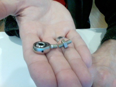
The most important thing with the gear leg fairings is to build them without any twist in them.   They come taped together from the factory, but Van’s fiberglass is usually so crappy for fit, I didn’t trust them.   The way you verify no twist is to put the leading edge on a flat surface and using a square, insure that both trailing edges line up.   Once that’s done, you can use the full-scale template cut from the plans to mark all the cut lines.   Easier said than done, though.  You really need two squares, one for each end, and another pair of hands, or at least a boatload of tape.   But I found a solution in our hangar that worked very nicely:

IMG_1710That brass thing is a piece of channel from one of those godawful floor-to-ceiling mirrored sliding doors, usually found in cheesy SoCal apartments that saw their last renovation some time before Saddam Hussein rolled his tanks into Kuwait City.   But it makes a very nice, very straight jig for lining up the trailing edges of the gear leg fairings.   Not only that, it provides an excellent platform for match-drilling the hinges.   Some of you are looking at this and saying “hey, those are the wrong size hinges!”  Yes they are.   But it’s what I had.   I used up all my 1/16″ piano hinge on various attempts at the cowl.   If it should come to pass that these hinges cost me knots and fuel, I’ll change them out, but at this point, I want to be done.

IMG_1711

A selfie, checking the alignment of the hinge.

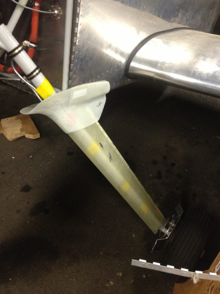
With those done, I could check out the fit of my intersection fairings.

IMG_1712

Upper intersection fairing fits, sort of.   It needs some work.   It’ll also need to be taped into position to hug the contour of the fuse and cowl, and then a couple of layups on top of that.   After that, it gets trimmed back to where it’s supposed to be.   Van’s fiberglass may be crap, but it’s better than mine and it sure beats fiddling around with modeling clay.

Monday was all about tying up as many loose ends as I could before starting on the wheel pants.   This meant, among other things, getting as ready for the inspection as possible.   I attached the ‘EXPERIMENTAL’ sticker to the roll bar:

IMG_1707

This is a bit redundant because the baggage bulkhead cover that came with the interior has it embroidered into the leather, but that won’t be installed during the inspection.   The canopy frame covers this one up when the canopy is down, but I don’t think that matters.   If it does, those stickers are cheap.

IMG_1709

This is required by the Feds to be in the airplane in plain view of the occupants.  It’s like a magic amulet to ward off the unadventurous.

Left Gear Leg

Left Gear leg

Left Gear leg works much the same way.

After this, I spent some time doing odd jobs.   I safety-wired the tailwheel chain hardware, then moved to the cockpit, where I zip-tied the wires made loose by the magneto troubleshooting and the addition of the OAT probe.    I also attached bolts in the center section per Van’s SB 12-08-14.   Apparently enough people forget this step that Van’s thought it merited a Service Bulletin.   Guess what?  I forgot it too.   In addition to the close-tolerance bolts that hold the wing spars to the center section, there are two on each side that secure the center section to the vertical bar on the wing spar.  These need some AN4 bolts in there to lock things down.

Part of getting airworthy is checking all the relevant SB’s and AD’s to make sure you don’t have anything hanging in the breeze that might kill you.   The rules on experimental aircraft and AD’s are fuzzy, and are interpreted by various people in various ways, because different sections of the FAR’s appear to contradict each other.    But the safe thing to do is check for AD’s and SB’s that apply to your stuff and fix them if you find any.   If I hadn’t gone through this process, I wouldn’t have found those missing bolts and the inspector would have.

When I moved on to the engine, I discovered some oil running down from the spacer on the right mag and at the oil drain fitting of the #1 cylinder.   This was alarming enough to merit a quick engine test.   I cleaned off the oil and wheeled it out to start up, to verify that the oil was new and not left over from the last time I had to loosen them up to get to one thing or another.

I did a quick runup and brought the cht’s up to operating temperature, but even with good, timed mags, it still stumbled off idle.   Advancing the throttle slowly would bring the RPM up, but moving it smartly, like I would for takeoff, killed the engine.   After consulting VAF and then my AFP manual, it looks like my idle mixture is set too lean.   This will need to be corrected, and I can probably do this tomorrow.  The good news is that I didn’t see any new oil in the spots where I found the drips, so it looks like the oil around the mag spacer was from when I had the mags off, and the oil from the #1 drain line is from the time I had to undo the fitting at the cylinder head to get at either the bottom spark plug or the EGT probe.


To Do: Wrapping up.

Let’s get ready for first flight.   These lists are known tasks.

Construction:

  • Pitot/Static test
  • Compass Calibration
  • Landing Gear fairings
  • Tighten ELT antenna
  • New Tailwheel Fork
  • Paint Fiberglass – Cowls, Gear fairings, Spinner, Wingtips, Stabilizer and rudder tips
  • Debug AP button on stick
  • Attach Placards and “EXPERIMENTAL” warning
  • Attach Data plate
  • Get another set of eyes on the FWF setup.
  • Rudder to Spinner checkout of every fastener visible.

Paperwork:

  • Flight test cards
  • Get logbooks for Engine, Prop, Airframe
  • Condition inspection
  • Program Letter
  • Weight and Balance
  • Call DAR – Check schedule, desired aircraft condition
  • Get Document pouch
  • Print blog, bookmark photos of me building
  • Put blog in binder

Ground tests

  • Engine run-in – use recommended settings on VAF


Gear Leg Fairings Continued

6 hours.

I found my missing length of piano hinge (hidden inside a piece of PVC to keep it from getting damaged), and took it and my intersection fairings up to OXR to see what I could get done.   I got up there and spent a lot of time pondering the instructions and plans.  I spent a lot of time doing that because this is real work about to be done here, and it involves fiberglass, and the cutting of things that affect the flight characteristics of the airplane.

The first thing I did was put the wheel fairing attach brackets on.   This is a stupid process if ever there was one.  I had to wrangle the engine hoist from down at the EAA hangar, walk it halfway across the airport, then lift each side of the plane  by running a strap around the engine mount so I could get the wheel off   I’m not shelling out a couple hundred bucks for some weird attachment, this seems to work just find.  With the wheel off, I could attach the bracket.

The gear leg fairings, on the surface, are not that complex.  They’re teardrop-shaped covers for the round gear legs.  The only tricky part is that they have to be built with no twist in them.   There’s a full-scale section of a drawing that needs to be cut out and used as a template.   This lets you know where you can cut the fairings, and the fairings are the same ones used for all Van’s aircraft except the -8 and the -8A.   They are attached by means of a couple of hose clamps and secured by a piece of piano hinge running up the trailing edge.   So they have to be cut straight, then there’s the hinge installation, then the alignment to the fuselage.   I got one part of one leg cut, and had to move brake tubing out of the way and cut clearance divots where that wasn’t feasible.

Other time was taken up by moving the late Jim Ayers’s RV3 (with the Walter LOM engine) out of the EAA hangar and down to his private hangar waaaay at the other end of the airport.   Ron and I rigged up a way to lash the tailwheel to one of the forks of the old propane forklift and he towed it, driving backwards, really slowly.   I followed him in his VW.  After we got back from that, we went for a ride in the Pacer.

Starting on gear leg fairings and wheel pants

6 hours.

My pre-molded intersection fairings arrived from Van’s this week, but of course I forgot to take them up to the hangar.    The last major bit of fiberglassery is the landing gear stuff, so I tried to get started on that today.   There’s a .063 plate that bolts on to the brake caliper and its job is to hold the two halves of the wheel pants together, on each wheel.   I made them, cut all the spacers, and installed them, then took them off, anticipating that I could just put them  back on as needed. But it’s impossible to access the bolt head on the inside of the brake caliper without taking the wheel off.   I made two attempts to bend a 7/16 wrench 90 degrees at the open end, one resulting in a broken wrench, the other a wrench with too wide a bend to fit inside the rim and access the bolt.

So I figured taking the wheel off would be the best option.  I searched the hangar in vain for a floor jack.   Those guys don’t have one.   The engine hoist I used before is down in the EAA hangar, but it was all locked up and I couldn’t get to it.   So that was out.

I did get the plans and the manual out so I could begin working on cutting the leg fairings to fit.    That didn’t take long, so I went up to the aviation department of O’Reilly Auto parts and picked up another tube of red RTV.   I finished the front baffle bead and the left mag duct, and also isolated a couple of things from chafing via the RTV Blob method.

Red Goo.

5 hours.

A shortish day, after Thanksgiving weekend.  But decent.   I got the pax side restraint system involved in addition to the pilot side crotch strap or “anti-submarine” restraint, as it’s called.  That took longer than I thought because of the number of times I had to hop in and out of the plane to find washers and other hardware and tools.

But now they’re both in.  This unflattering photo is just to show that both seat belts are hooked up.

IMG_1687

So I went on to the red goo.   I’ve been putting this off, because of my usual aversion to non-solids, but it was finally time to RTV the baffles.   Squeezing a tube of red RTV into all the places it has to go is really hard on the hand muscles, especially when you have to get the nozzle into nooks and crannies now blocked by FWF equipment.

IMG_1685So I’m not the best RTV’er in the world, but I think the bases are more or less covered – a bead running along the baffle meterial, and anywhere light gets between the baffle and the engine.   OK, maybe not everywhere, but everywhere I could get the stuff in there.

IMG_1686Oops.  Didn’t get around the right magneto blast tube.  I’ll have to get that later.

But I was sure to get RTV into all the gaps between baffle and oil cooler, because that’s kind of important, and as for other leaks, we’ll have to see what happens to CHT’s in flight.