This is more of a checklist for me than a report of actual work done, but here’s what i need to do to finish the wings:
Seal/test fuel tanks
Install nav antenna in wingtip (on the way from AC Spruce)
Install nav/landing lights in wingtips (on the way from CreativAir)
Run power and antenna wires from wingtips through conduits to wing roots
Run pitot/AOA plumbing to wing root from pitot mast location (order this from SafeAir)
Make wingtip connectors for lights/antenna.
Figure out whether or not to close up the wings, and if so, install pitot/AOA mast and probe.
Once these things are done, I believe the wings are finished. Then I have to store them in the garage and build a wooden cage around them so they don’t get bashed by various comings and goings for laundry and yardwork. This can be done by a few 2×4’s framed outward from the wall and covered with a thin sheet of plywood.
Things to finish wings
So now what.
2 hours.
Finally got what I needed from Spruce to finish the wing conduits, and those are now done. Proper aluminum Adel clamps all around, no interference with the pushrod. Also temp-installed the fuel senders. After a lot of agonizing about how to do this, I decided to bag the fuel return lines for now. If I get into a situation where I need a new engine and that engine needs a fuel return, I’ll pull the tanks off and plumb it then. I could do it now, but why? I guess the advantage is being prepared for an eventuality, but it’s still going to be a lot of extra work, and those fittings are pricey, from either Van’s or Spruce. And another thing: trying to correlate Van’s AN SPACER 6D with a spruce part number was nigh impossible. Not only that, I’m not sure what sizes to use for a return line. The Eggenfellner site says to use 5/16, the fuel feed line is 3/8’s so returns of that size would make sense, but a lot of guys on VAF would have done it 1/4 if they had to do it again. I don’t need it that badly, so screw it. Moving on.
I’ve ordered strobes, nav, and landing lights. I went with CreativAir’s LED nav light and 75w halogen landing light combo, and a 60w/6 way strobe package from Strobeguy. I also got the Archer nav antenna from spruce. All this crap is going to go into the wings and so is the wiring. I still have to proseal the fuel stuff and test the tanks (dread), but wiring the antennae, strobes, and lights should be fun, and not in the usual snarky way I say things are fun. I’m looking forward to it.
What this means is that I can’t yet shove the wings into a dark corner for a long time and go full tilt on the fuse. I need all that above-mentioned crap to finish up the wings, but if I can get the tanks sealed, then maybe I can save that wingtip stuff for much, much later. I’m not worried; I’ve got a 3/4″ wide conduit down each wing. Wiring wingtip goodies is going to be a snap.
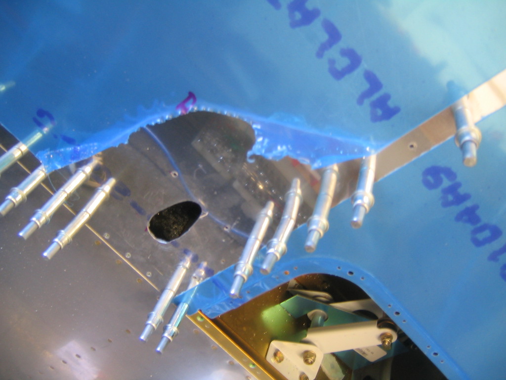
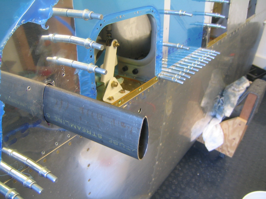
This is the PVC conduit running along the pushrod. No clearance issues here.

Top of the pushrod’s arc. No way is this going to clang.

This is the conduit sticking out way past where it should at the wing root. I’ll trim it, eventually. The red crap around the edge of the lightening hole is irrigation drip tubing, split down one side and fit over the edge so the pushrod doesn’t bash around and ding up the primer.

A look at the tank access plate, with the sender temp-installed. The little blue AN fitting below toward the leading edge is for the vent line. The two clecoes on each side are holding on to an anti-rotation bracket that slips over the tubing nut on the other side of the plate where the big blue fitting is. That’s where the fuel pickup is. That will get prosealed and riveted.

Wings moving along.
4 hours.
Finished dimpling bottom wing skins and got the access doors done. This did not go perfectly. I didn’t set the clutch properly on my powered screwdriver, so I snapped one of the 6/32 screws for the forward edge of the left outboard access door. No big deal, except I don’t have a replacement 6/32 K1000. I wish I’d done this last week before I put in my order from Spruce. I’m not ordering a lone bloody platenut. I was going to wait until I messed something else up, but that didn’t take long; I did it as soon as I got to the fuel senders. To make the fuel float work, you’re supposed to bend the float wire 90 degrees about 3″ back from the float, then cut the wire off 3″ down from the bend. This insures your float goes all the way to the top and bottom of the tank. Well, what they don’t tell you anywhere on the plans or the float instructions is that you’re supposed to leave enough wire on the end to bend 90 degrees and stick it through the hole in the sender’s pivot. This keeps your float from flopping around. I found this out on VAF after I’d cut the wire. I only used 1/8″ for this bend, so it might still work just fine. If that’s not cool, I can make a new float wire out of extra piano hinge, which someone else did.
I’m also not sure what type of bolts/screws to use when fastening the sender to the access plate on the tank. Drawing 16A has all the fuel tank details, but I can’t find that tidbit anywhere.
The other thing I did was start pulling some pieces out of the tailcone and clecoing/leaning/stowing them where they’re supposed to go on the airplane. It saves some time looking for stuff, and reduces some of the psychological impact of such a huge pile of parts.
Wing conduit, and a couple of fiddly bits.
4 hours.
Spent a whole lot of time figuring out the best way to run PVC conduit down the big lightening holes in the left wing today. I’m sort of doing the Mickey Coggins method, but probably not as well or as precisely. I made a bunch of L brackets out of a forward HS spar I’d ordered a while back when I thought I’d have to replace most of my HS, then clecoed Adel (fake ones, from Ace) to them attached to the 3/4″ PVC conduit. Lots of trial and error, moving things into position with various clamps and such, testing for fit and interference with the bellcranks, figuring out which ribs to clamp them to. Once I got a combination of bracket, Adel clamp and conduit that sat well and gave maximum clearance to the bellcrank, I clamped it down and marked the position on the rib. Then I made a template out of some scrap, which made it easy to determine the bracket location on the remaining ribs. Of course, here I am, trying to hold three pieces of metal in position with the intent of putting a drill bit through them when I grasp the fact that I’m doing it the hard way, as usual. The little 1″ cleco clamps you get with the tool set are like extra hands in a situation like this, and I’m a dumbass for not realizing it earlier. Clamp on the template, clamp the bracket, drill the bracket, move on to the next one. I primed the brackets, the outside of the aileron pushrods, and the pitot mast while I was at it, then riveted on the left wing brackets. Right wing brackets are in position, I should be able to deburr, prime, and rivet them into position tomorrow. Then, I wait for a bunch of AN hardware to show up from Spruce.
Also, my package from MSC showed up. Should be a new Burraway, some spare blades, and something else I forgot about.
Some ugliness.
Yesterday when Dan was here, he pointed out the ham-fisted way the left HS inboard ribs were put together. He was right. It’s ugly. Two rivets are close to minimum edge distance, if not over the line, and now that I see that little section of the HS (Months later), it looks like a team of chimps went to work on it with socks full of ball bearings. But I so want to be done with the empennage. I sent photos to Van’s, and they said yeah, it’s ugly, but it’s ‘hard to imagine this will cause any problems structurally.’ So I’m going to move on, and cover it up with the empennage fairing when the time comes. If it continues to drive me nuts, like some aluminum telltale heart pinging away aft of the baggage compartment, I’ll fix it by replacing the left HS inboard ribs.
Oh, one more thing.
Yesterday, my .093 Burraway developed an oscillation, due to me pullingit out of a hole at the wrong angle. In the foolish attempt to bend it back into shape, I snapped the shank right in half. That was a big ‘Oh frak’ and not the Galactica pronunciation either. Cost is $TBD in treasure, and a nice gouge in the base of my thumb from the snapped end in blood.
TC visit today.
4 hours.
Dan C and Scott F stopped by today and we went over the progress to date. It worked out great! The only squawks were some bolts without enough threads showing, some with too many, and a question of whether or not the left inboard HS ribs are outside minimums on a couple of rivets, and a suggestion on how to do the flap hinge pins, which brings us to today’s actual work.
Afterwards, we grabbed a bite to eat at Spitfire, then I watched Scott’s IO-390 powered RV7A hop into the sky like an ICBM. Back home, I farted around for a while, trying to decide what to do first. I did all the bolt squawks on the emp, then put the emp parts up in the attic, awaiting Van’s word on the rivet status of the HS rib. Then I did the flap hinges. I cut out 2 eyelets on the flap and one on the wing and ran the hinge pins in from the center. I bent them back and fastened them to the flap brace by means of a small plate and a CS4-4 rivet. Probably coulda just safety wired them below the wing, but this way the pin ends are tucked away out of sight. I did the left wing, and i’m almost done with the right wing, just need to make a hold-down plate for the pins and the flaps they izz installed.
Still waiting on my Dynon pitot/AOA probe.
Right flap and pitot mast.
6 hours.
A few things happened over the last few days, but I’m going to lump them all into one entry rather than a lot of little fiddly bits. Got the right flap installed. Went faster than the left one, since there was a little less puzzling about what to do. I also managed to do the end rivets with AN470’s instead of the CherryMax rivets you’re supposed to use (if you’re quickbuilding), so I’m pretty stoked about that. The hinge pins go in easily enough, with some resistance, but I can push them all the way in by hand. I also drilled the right bottom skin. Still need to deburr/dimple both bottom wing skins, but that can wait. Yesterday, my SafeAir1 pitot mast came in the mail, so today I drilled it to the skin and spar. Cutting the hole for it was a breeze.. i got the metal bit for my RotoZip and it did a fine job. Again, still needs deburring. The Pitot mast is raw steel, and it had some rust scale on it, so I had to sand the hell out of the inside. I’ll sand it again and paint it this week. It won’t need to go in until I close out the left wing, which won’t be for a while. I picked up two 10′ lengths of 1/2″ pvc for wing conduit, now I just have to spend some time fabbing brackets to mount it to the ribs. Since I’ll be using the conduit for wing wiring, I can use both the pre-drilled and grommeted holes in the ribs for the Dynon pitot/AOA probe’s tubing. The probe should arrive in a couple of days. I’ll probably drill the probe to the mast, paint the mast, then put the whole thing away until bottom skin time.
Here’s the hole for the pitot mast. There’s a nice scratch near the hole where the bit slipped. I guess we’ll be sanding and priming that area.
Here’s the RotoZip. The plasting tube sticking out goes to an adapter for the shop vac. Sucks the dust out while you’re running it, but it also gives you a good look at the bit and where it’s going. Just don’t be looking down that tube up close without eye protection or bad things will happen.

Here’s the mast, test fit.
Tomorrow, Dan Checkoway and Debris (a TC in training) are coming out to have a look at my work, so I got the skins unclecoed and got the tail parts down out of the rafters for them to look at. Some of the metalwork is downright embarrassing, but I’ve been trying to follow the rules (edge distances, no pillowing, etc) and I think it will be safe, just not pretty in some places. Like an old Volvo. But the most obvious question here is why am I resting the rudder and Vstab upside down on the floor? It’s not on the floor, it’s on a layer of folded up packing paper, and it’s the only way to lean the assembly against anything. The vertical stabilizer doesn’t really weigh much, and the skin around the counterbalance is pretty thick, so there you have it.

Tomorrow, I’ll report all the gotchas the TC’s find that I didn’t catch. Hopefully the list won’t be too long.
Oh, and if you’re reading this and you haven’t already, join EAA. Do it right now. http://www.eaa.org
Left flap attached.
6 hours.
Left wing: installed flap brace and flap hinge, aligned flap. This was a bit of a quandary, and I might wind up redoing this, and here’s why: With the aileron in neutral, the flap, based on where it was drilled, is about 1/16 short of the trailing edge of the aileron. Now, I drilled the flap hinge on this way because I wasn’t comfortable with the amount of distance from the rivet to the edge of the hinge. I’m going to go out on a limb here and guess that as long as the other flap is done the same way, it’s not going to affect flight. A lot of folks on VAF wound up getting the next wider type hinge for this op. I’ll ask Van’s what they think, but it seems silly to have to get a different type of hinge than the one included in the kit just to give you edge clearance between the rivet and the edge of the hinge. So here’s what I did: I used the ‘Dan’ method of using keeper rivets to hold the flap brace and the skin together while I clamped the hinge and flap to the skin and brace. After drilling the hinge is done, you drill out the keeper rivets and countersink the flap brace just like the plans say, then you put the whole shebang back together like you’re supposed to. One mild-to-medium suck: My cheap Arrow blind rivet squeezer won’t take a 3/32 rivet, which is what the CR3212 CherryMax rivets on the ends of the flap brace are. I think I can make at least 4 of them happen with regular AN470AD4’s, but I’ll have to either find a decent alternative or get a rivet squeezer capable of dealing with a 3/32 shank. Other than that, it’s all good. the flap moves freely, the pin goes in without too much trouble, and the end result looks suspiciously like an airplane wing.
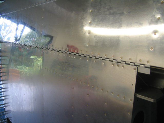
Here’s one of a keeper rivet and the clamp on one end holding the hinge in position. You progressively drill and cleco your way down the line. Then you can take the clamps off.

Gap between flap and aileron is the plans-specified 1/4 inch. My camera doesn’t do macro, so it’s a blurry mess. I spent the money on a plane.

Here, we’re looking down onto the rear spar. I used a slew of AN470 rivets to hold the brace in place on the spar while I hung and drilled the hinge. This shot is right after I’d gotten all the hinge holes drilled, except for the keeper rivet holes, which got done later.

Here’s the finished deal. By ‘finished,’ I mean everything done except the line of holes in the bottom outboard skin, which is currently clecoed on temporarily.
Here’s the big picture. The outboard bottom skin is clecoed on, ready for drilling. I need to get this out of the way so I can stow it while I have fun with conduit and pitot lines.

Bellcranks, ailerons, and some pics.
6 hours.
After some adventures in tubing, it was time for some good old-fashioned mechanical hijinks, this time involving the bellcranks. Since I’ve got the quickbuild kit, the build sequence is, uh, fragmented. Supposedly, during the wing build, the plans and manual stop holding your hand and you need to just figure stuff out, which is fine, but it really makes you double-triple-quadruple-check everything before you cut metal or stick it together. In this case, the tubes and the aileron brackets were two discrete operations that were done separately. The aileron brackets (wing side) I did a couple of months ago while waiting for some rudder parts to arrive, and the tubes I did last week. This week, it was all about the bellcranks, which were good old fashioned meat-and-potatoes mechanical fun. I did have some issues cutting the aluminum spacer tube, which you are given just enough of to do right the first time. In my case I had to grind off extra material on the ends to get a flat end, thanks to my cheesy bandsaw, which is probably just more out of alignment than anything else. I had enough tube to get the left aileron on, and get it hooked up to the bellcrank via the short steel push tube, and I think it works OK, no binding, free motion. The good folks at Bill’s Air Center were nice enough to give me a cat-food can of aviation grease for the brass bushings in the bellcranks. I didn’t finish all the stuff on the right aileron though. I don’t have enough aluminum .058 wall 3/8″ tubing to make the spacers for it, so it’s on there in a temporary fashion until my spruce order shows up. But both bellcranks are in, lubed, and torqued, so we’re ready to rock.
Here’s the left aileron, in place, bellcrank installed. The blue piece near the bellcrank is the jig to hold it in the neutral position while aligning the aileron:

Close up of the aileron bracketry. Got good rivets on the pushrods, thanks VAF! The alignment of the ailerons is probably bogus, but here’s how I did it: The distance from the white aileron bracket on the aileron to the top of the reinforcing angle on the wing is measured with a micrometer in two places, down near the hinge and up near the end of the angle. When the measurement is the same, or within a few thousanths of an inch, that’s where the neutral position is, and the threaded bearing at the other end is adjusted accordingly before getting bolted to the bellcrank. I’m sure this will change, but it’s OK for now:

This is a shot of the right side bellcrank assembly. No jig on this one, I think I only got one and it’s on the other wing, unless it’s floating around in the bottom of the canoe which is where I’m storing a lot of parts until I get some shelves put up in the shop. I hope to finish this process this weekend while I’m working off turkey and stuffing.
