6 hours.
Quick update: Baffles trimmed, front baffle bracket fabbed, top inlet ramp trimmed,
Pondering airseal fit. I just don’t friggin’ get it.
6 hours.
Quick update: Baffles trimmed, front baffle bracket fabbed, top inlet ramp trimmed,
Pondering airseal fit. I just don’t friggin’ get it.
7 hours.
When I made the entry for yesterday, I was dead on my feet. After a day or two of standing/working, I sometimes don’t have the patience to write well, or clearly, and I certainly don’t have an excess of desire to deal with photos. I’m sure there’s some fancy wordpress widget that can handle it, but when I started this project, ‘blogging’ was a new buzzword heard only in elite circles of of the technorati, and as yet had no good tech for displaying images other than the tried and true html code, which is what I use, and still use.
Along with that, when I’m on the “here be monsters” part of the instructions, I don’t often stop to take photos because I don’t want to lose my train of thought. I envy the photojournalist’s muscle memory of shooting constantly while engrossed in other activities. I just ain’t got it.
So this entry is just a slew of photos, with comments as to what was going on, and hopefully they’ll tell some of the story of how I arrived at a solution for the interlocking puzzle of front-governor, snorkel, and baffles.
Like I’ve mentioned before, the O-540 front baffles from the RV-10 kit get dragooned into service on this particular -7. The biggest headache is finding all the chickens, all the eggs, and turning them into ducks, which go in a row. Barnyard metaphors aside, it becomes an exercise in problem-solving to figure out what to do first. The first thing to do is to fit the snorkel. I won’t go into that here, because it’s been described elsewhere, but the only way to get a solid enough structure from which to take any reference for cutting or fitting the front left baffle is to get as far as you can on the snorkel. This means riveting the side baffle and drilling the left front inlet ramp to fit it, with all the bends and adjustments done.
Like everyone else says, don’t trim the front of the inlet ramp until the last minute, because you’re going to need it to form the front air filter retainer angle, which is simply a bend in a section of the inlet ramp where the air filter edge stops. Mine’s just on the nice side of acceptable for this purpose. Making this bend also stiffens the inlet ramp, and that’s a good thing, because by the time you’ve cut the gaping maw of the air filter opening, things get a little wobbly.
From there, you can fight with the snorkel and the air filter retainers, and at the end of the process, you have a detachable airbox whose structure provides a rigidity suitable for measuring the final inlet floor angle.
This angle was marked on the engine case, but sure enough, it drifted around a degree or so during the install.

See that flat pad just below the governor? That’s where I marked the initial angle of the inlet ramp. This is done with the lower cowl on, because it’s necessary to make sure the inlet ramp comes up to the inlet on the fiberglass lower cowl. Also, don’t do like I did, make sure you cleco all your baffle-to-case hardware on so you can work without every bump moving something out of line.
I didn’t photograph this process but the way I measure’d the angle is by using a cheap plastic angle measuring thing (don’t remember the actual name of the device) which is like a protractor with a couple of arms and dials on it. You can use whatever you want, but the reference for this to line up the vertical are the two aft studs for the governor mount. With one arm of the device on those and the other laying on the inlet ramp floor, you get what you need. The governor should be off at this point, to give you room to work.
From there, it’s no big deal to transfer that angle to the O-540 front baffle, which has a sharper angle than the 360 baffle, and cut off the excess to line it up with the governor and the inlet floor.
With that done, you have a front baffle that more or less fits where it’s supposed to go. I didn’t take photos of the air filter retainers, VA-132-C and D, which hold the air filter in place inside its hole, but you need to make sure you have these on when you’re doing the final position of the baffle.

This photo shows the lower edge of the baffle laying along the inlet floor just inboard of the inboard air filter retainer. This is important, because the left front baffle needs to be detachable and accessible, as does the filter retainer.

The factory-formed tabs on the baffle are no longer there after the bottom has been cut away to match the inlet ramp angle, so you have to replace them with something. This is the first attempt. Initially I figured I’d only need to do the long side, but this isn’t really a good solution.

This little whisker proved to be the source of much head-scratching, pondering, and measuring. This forms to the angles of the baffle and the inlet ramp, replacing the tabs that were sheared away during the fitting of the baffle.

Like so. This provides a good place to mount the platentuts that hold the baffle to the inlet ramp. It looks fine now, but getting to this point was insanely difficult. At some point in the build, you realize you’re off the map entirely, and you wind up being designer, engineer, and installer, sometimes all on the same day.
This is why I can’t stress it enough: If you’ve never built a plane before, or you don’t have a lot of experience with fabrication or mechanical work (like working on airplanes, for instance), don’t deviate from standard configurations or construction, because you’re going to get your ass kicked. The whole reason I’m in this mess is because I bought a weird engine. If I had to do it over again, I’d have gone with the recommended 360, with its aft-mount governor. Would have saved two or three weeks, possibly more. Seriously.

Anyway, back to the narrative. With the angles cut, bent, deburred and drilled, the platenuts go on, then this piece gets riveted to the inlet ramp.

The right hand side is similar, except in this case I’m using a slightly thicker piece of angle stock, since there isn’t as much of it in contact with the baffle. Not shown in this photo is the small piece of angle on the front edge of the baffle, which provides enough beef to keep everything solid. You can also see the conical gusset clecoed into place. This is an interesting bit of business, because the aft-most hole on the conical gusset goes through the inlet ramp and the bend in the side baffle. The two forward most holes are done with flush rivets so the airseal material can lay flat against the surfaces.

From time to time, it’s necessary to put the lower cowl on to check fit and lineup. In this shot, you can see a slight conflict between the aft platenut on the cowl and the forward edge of the baffle. Trimming away a small bit of the baffle fixed this.

This is another view. The aft angle piece took care of the gap between the baffle and the inlet ramp frame, but there’s still a small one on the first bend. This is why the archengineers of aerospace spec’d out high-temp RTV.

Back to the left side. It’s a little hard to see, but there are four flush screws holding the front baffle to the angle from earlier, which is riveted to the inlet ramp.

Here, everything is screwed on and riveted, except for where the two upper baffles join. I’ll have to fabricate a bracket that will connect to the case bolt just above the governor drive gear. Sorry for the blur. the iPhone 3g has some issues compensating for the light levels present in my shop during daylight hours.
The next phase of this is to cut down the top edges of the baffles to allow the top cowl to be installed. This is another iterative, bit-by-bit process, taking care not to remove too much metal, but enough to allow the cowl to sit where it’s supposed to with the hinge pins installed.

As you can see from this photo, there’s plenty of metal that needs to go away before the top cowl will sit where it’s supposed to.

I started the rough cut, and rough is definitely the word for it, but the idea is to get the cowl to fit again. There isn’t too much reference for this step, in the plans or on the Interwebs, But it becomes obvious what to do after a while. There was a lot of anxiety reaching this point; nothing on this up to now has been simple or easy, why should this be any different? But eventually, you just need to sack up and start trimming the baffles.

Just check for fit frequently.
After this is done, you’ll need to make the final trim, which is 1/2″ of clearance between the top edge of the baffles to the cowl, uniformly, all the way around. There are various methods for doing this, although I foresee a little more chicken-and-egg when it comes time to do the upper inlet ramps, which are fiberglass, and attached to the top cowl. I’ve decided I’m going to cut down the side baffles to fit the upper inlet ramps rather than having them ride outside of them, as some have done. I think this will provide a better seal and reduce the amount of dependency on interlocking parts.
Mostly the process involves deriving a reference line on the baffles to use as a cut guide. Some have done it with paper clips: put a crap-ton of paper clips on the baffles and the cowl pushes them down and lets you mark along the contour. Also there’s the wheel-and-sharpie method, where you cut the end off a fine-point sharpie and put a 1″ disk of aluminum on the felt tip, rolling that along the contour of the cowl to mark the line, although I don’t see that working real well except for anyone besides Plastic Man or an octopus, given the space constraints you have for arms and hands.
4 hours.
Prior to any fun stuff with the prop, I clecoed on the forward top skin. I did put clecoes in from upside-down along the front in a couple of places, But I think I’m going to take them out, because as somebody on VAF wrote, you’re trying to match the cowl to the skin, not the firewall flange.
So, remember that fancy purple custom spinner on my prop? Turns out there isn’t a really good way to mock that up, short of scoring a junk Hartzell C2YR or C2YK rear hub half. Here’s why:

The stock spinner is a flat disc that can be mounted to the prop flange with six bolts, at the end of 2 1/4″ spacers. This one mounts to the back of the prop hub using a 7/8″ spacer between it and the hub, to get it clear of the hub itself. No place to attach bolts for the prop flange.

Here it is again from the side.

Measured from the back of the prop flange, It’s a little under the 2 1/4″ spacer length called for in the factory setup.
So a command decision was made to just hang the prop on the engine and fit the cowl based on the real deal instead of the mockup. This is acceptable, lots of guys have done it to no ill effect, other than it being an obstacle in the shop. However, with the blades set to vertical, it’s not in the way all that much. Initially I was going to see if David could help me hang the prop, but then I remembered, hey… I have an engine hoist. The installation guide in the prop manual recommends using a sling to position the prop anyway, so the hoist got yet another use.

I wrapped some blue masking tape around the blade roots to protect them from the straps, enhancing the plastic wrapping the prop shop put on the blades when I had it resealed a few months ago. This gave me a pretty decent setup to get the prop hub flange lined up to the crankshaft flange.

This is where it got interesting. The actual installation has you putting six studs in the prop flange, torquing them, then installing the prop to those via castle nuts with spring pins through them. I don’t have that option. You can see from the top pic that my prop came with the studs, castle nuts, and spring pins installed already, so the process became this:
Get the prop lined up as nicely as possible
Get all the studs started
Keep hand-turning each one a couple of turns until after an eon, the prop seats on the crankshaft flange.
This took a while, and they’re not torqued down at all. The whole point of this is to fit the cowl.

The top half of the pepto-pink cowl came down from the rafters to be sat atop the engine (from which I had previously removed the baffles in their current state), and I have to tell you, the pink/metallic purple combination is striking and eye-catching, in the worst way possible.
Next is
7 hours.
Apparently, 7 hours is enough time to royally screw up a cylinder baffle. Case in point:

The #4 cylinder baffle holds the oil cooler on the aft section of the baffle. The way this is supposed to work is that the baffle is made largely of 4 pieces: There’s the part that connects to the #4 cylinder head, the part that holds the oil cooler, the part that covers the inboard part of the crankcase, and the stiffener that holds parts 1 and 2 together and gives it some beef so the oil cooler doesn’t rip the baffle apart in all the vibration. The plans call out a distance of 3/8″ from the outboard edge of the baffle where it joins parts 1 and 2. Fun fact: If you stick to this dimension, you don’t get enough room between the drill-through holes of the oil cooler doubler and the angle on part 1, which means you can’t install platenuts. Part 4 has pre-drilled holes which supposedly line up with the holes in the oil cooler doubler. The plans then say “keep the oil cooler as high as possible for maximum efficiency.” Well, that’s neat and all, but if you do that, you get out of alignment with the predrilled holes, and everything’s a mess.
Another important safety tip is to leave cutting out the big rectangular hole for the oil cooler airflow until AFTER the whole mess is drilled. Long story short, I wound up making a huge mess, with holes drilled way outside acceptable parameters for edge distance, a rectangular opening about 1/4″ off from where it should be, and a generally bad day. So I have to order new parts from Van’s and call it a lesson. Also, the plans say to follow the callouts on drawing OP-27A. I don’t have that one, I have drawing OP-27, which is probably the same thing, but I have to check.
So after setting that aside, I went on to see if I couldn’t screw up the #3 cylinder baffle as well. Lo and behold I did not.

This one clecoed together nicely. IN the above photo, you can see the flange for the cabin heat intake. A little piece of screen goes between this and the baffle to keep the grasshoppers out of your cabin heat muff attached to the exhaust pipes.

Here are the two sections of the #3 baffle in an intermediate state of completion. Notice on the lower right, the cutout looks a lot like a Lycoming valve cover. The two doublers there are where it screws to the cylinder heads. One thing you have to do to get these things to fit right is to trim away the excess gasket squeezing out from under the valve covers.

Another shot of the #3 aft section. You can see the bug screen sandwiched between the flange and the baffle, as well as the tab that mounts to the crankcase. Bit of fun, that. In order to get to this part with a screwdriver, you have to dismount the oil fill tube from the engine. Nothing else will work, not even my miniature ratched screwdriver. That’s fine, I just have to remember to safety-wire the oil tube again before I run the engine.

A test fitting. This is a pain. Install, figure out where the baffle rubs on the crankcase, uninstall, grind down baffle, repeat.

From the back. See how deeply buried that mounting tab is? It’s hard to see, but there’s a piece of black PVC tape covering the hole for the oil fill tube.
I also started messing around with the center mount bracket, which requires a little bit of moving the injector lines around to keep clear. This steadies the middle of the baffle in back and connects both #3 and #4 baffles together at the center.
Next is to continue on with the #1 baffle, whichever one connects to the one I just built, because I can’t do squat on the other side until I get the new parts for #4.
12 hours.
This is a tale of the 36 hours beginning Thursday the 3rd. It started with a text from Shelley, who said my EFIS had arrived from MGL Avionics. The unboxing revealed this:

This is the MGL Stratomaster Odyssey EFIS. There are many like it, but this one is mine. I hooked it up with the backup battery, plugged in the AHRS and compass and flew over SMO. My house is about a mile away from SMO, so I set the barometer high enough to see over the hills and rolled the sensors around. The EFIS responded brilliantly. Setup should be a snap. After that, I put it away in its box and went back to work. While I was there, I got a call from Tim at Tim’s Aircraft Engines, who informed me that my engine was done. Friday morning I went to pick it up. After some interesting work with the hoist, the guys managed to get it into the back of the truck and get it strapped down and I was able to bring it home.
So, to recap. We started with this eBay special:

Gutted it for the conversion, but found spalling on the lifters. Boo.

This stage is pre-assembly at Tim’s Aircraft Engines:

And here it is coming out the back of the truck at home on Friday:

It’s so. Freaking. Beautiful.

And here it is, ready to go.

Dave had promised me he’s stop by and lend a hand this weekend. He did, bright and early Saturday morning. He bucked some rivets on the antenna and fuel fitting doublers that would have been impossible for me to do with anything but pop rivets. After that, we were originally going to lay out and cut the panel, but I said why not hang the engine instead? I’ve got all the truly annoying firewall stuff done, Dave’s here, and I can cut the panel on my own.
So I set up the engine hoist (this thing has been useful more times than I can count now).

Getting ready to lift it into place. Some guys have done this on their own, but I just don’t see how.

Shelley stopped by the shop to see what all the cursing was about, and fortunately she had her camera.

I asked her to document the process. It wasn’t that bad, really.

Watch your fingers, guys.

The last bolt is a complete bastard. If it isn’t, run out and buy a lottery ticket right then and there.

No, I’m not about to beat the engine into submission with the Red Stick of Death. I’m holding the engine hoist bar above my head in celebration. This is the Tin Man’s heart transplant right here, a significant milestone on the way to being finished, or at least flying.

One thing we had to do was take the fuel servo off and rotate it 90 degrees so the inlet was on the side. This is per the AFP manual. This has the effect of putting the control arms for mixture and throttle on the bottom, where there’s just barely enough room to get control cables to them. Unfortunately, none of the hoses supplied in the Van’s FWF kit work for this configuration, so I’ll have to send them back and get some custom ones made at Earl’s.
(Update: turns out the hoses are probably OK. I forgot that between the firewall and the fuel servo is a rather large and unmistakeable engine-driven fuel pump that has a hose going both into, and out of it. This will more than make up for the discrepancy in length.)
Charged with the rush of success, that being measured by the fact that the engine didn’t fall off and crush one of us to death or disability, we tackled the exhaust. After losing an hour to the fact that we both caught a case of the stupids when it came to the heat muff, we got it all hooked up. trimming the stainless steel support tubes dulled up my bandsaw blade, but it worked long enough to get the job done. Fortunately I had a spare.
Today was rather anticlimactic. All I did was fabricate the mount for the EFIS backup battery and ponder bracketry for a while. Of course, it was Super Bowl Sunday, so we all went over to Dave and Peggy’s to watch the game.
Dave, thanks a gazillion for all your help. You get the first passenger flight, if you want it. And if Shelley doesn’t.
2 hours.
That’s not saying it won’t come apart again. It’s currently in this state:

I think I’m not kosher on the amount of threads showing on the bolts holding the wheel pant bracket on one leg, but I can sort that out tomorrow. But I have this theory: If things are assembled with all the requisite parts, those individual parts are less likely to grow legs and wander under appliances and places of storage to hang out with the dust bunnies. It’s like the Phantom Graveyard of Lost Hardware under there, like that scene in Heavy Metal when the B-17 crash lands on the island full of derelict planes, abandoned spaceships, and zombies. But instead of zombies, I have an assortment of fasteners and other hardware.
The gear is ready to rock, but I need to get fire caulk so I can finish up the firewall installation stuff and put the engine mount on. Then I can put the plane on the gear, just for a hoot . Tailwheel’s on, why not give it a test roll?
The engine is still at Tim’s. He’s backlogged, and my engine is all torn down, waiting for inspection. I’m not in a hurry, but I am in a hurry to find out how things cost, because I need to know what my avionics package is going to look like. The way my luck runs with engines, I’ll probably have enough left over to equip 313TD at about the same level as Kern and Rinker Buck’s Piper Cub.
1 hour.
Last night I dismounted the engine from the stand and stuck it in the back of the truck. I’m really glad I didn’t throw out the plywood stand it arrived on. Yesterday, I spoke with Tim at Tim’s Aircraft Engines. A standard teardown and inspection is going to be around $6200. Ouch. But whatever, I need a safe engine, right? I have no way of knowing what happened to that airplane between 951 hours (last engine log entry) and 975 hours. It could have been prop-struck, Maybe sat on the ramp and only flown once a month for two years (I seem to remember the seller telling me it was pulled from service in 2001 or 2002), who knows? But Tim is going to pull it apart, magnaflux it, figure out what’s wrong, then tell me what’s up. He can also rebuild my cylinders and put my sump and FI system on it.
At this point, I’m beyond my ability or capacity to mess with this engine. I don’t have the tools to split the case, or check the components properly for wear. And I really don’t trust myself to put it back together, even if I had the proper facilities to do so. A cylinder or two, I can handle. Maybe building up a kit engine from new components. Not this. I’m going to pay through the nose for it, but I will have a safe engine of known condition. I hope. And if I wind up paying 20 grand for the service, i’ll know better next time, and that’s not to buy an engine off eBay without absolutely knowing its pedigree. I bought this engine before I was ready, and when used O- and IO-360’s were relatively rare. So now I get to pay the price, in stress, inconvenience, and a near-spinebreaking torpedo to my savings.
7 hours.
Yesterday, I recovered from my cold enough in the afternoon to get going on the engine. This means I rolled the engine out on its stand into the middle of the room where I could work on it and prepared to take off a cylinder so I could have a look at the cam lobes. This would be the step that determines the way forward, because if the valve train parts are trashed, I have to send the engine in to a rebuilder and I’m looking at the possibility of a very expensive repair, because there’s no way to fix the camshaft or the lifters without splitting the case, and that STARTS at around 2 grand. So off we go. First thing was to de-pickle the engine. This meant draining out all the oil I’d had filling up the case since I bought the engine in 2008. There was oil hiding everywhere in this thing. Even after draining out the oil, every time I moved the crank or tilted it, more would come out from somewhere. But that’s kind of the point. Parts submerged in oil don’t corrode. The crankshaft bore gave me a bit of a scare. When I pulled the end cap off and fished out the old sock that had been shoved in there to keep the oil in (WTF?) I discovered a load of gray sludge in the crankshaft bore. This is lead and oil, congealed into a gray goo, like bad nanotech. At first I freaked, I thought this stuff was from the sock partially dissolving in there. The sock wasn’t dissolving, but the lead sludge was now all oiled up and nasty. I scraped that all out with a wooden tongue depressor and moved on. After I got most of the oil out, it was time to have a look inside. I went for the #3 cylinder, because it was the most accessible. The #1 was obstructed by the governor and bracket. Taking a cylinder off one of these things is not really that big a deal. Follow the manual, don’t lose any parts, and dont’ force anything, you’ll be OK. So that’s what I did.
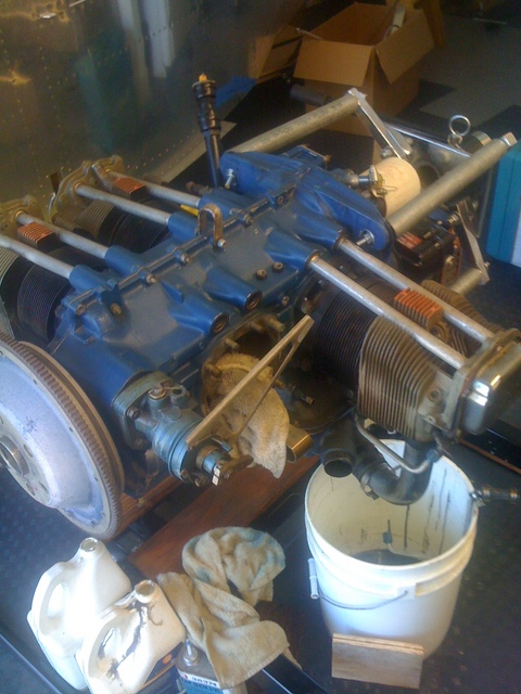
Lots of rags to pick up oil drips, and another one wrapped around the connecting rod so it doesn’t bash on the case and damage it. This would be bad. To get this far, I had to take the rocker cover off, remove the shroud tube retaining clips, then remove the rocker arms. After that, I could pull out the pushrods, and pull the shroud tubes through the cylinder head. At that point, the cylinder was free to go, after removing the oil drain line. With each one of these steps, more preserving oil dribbled out, hence the progression of rags on the floor. The drip pan doesnt fit under the engine stand, nor is it wide enough to catch oil from opposing cylinders. So what was the point of this? Oh yeah.. have a look at the camshaft and tappet bodies. Maybe that’s Greek to you, but essentially what happens is this: The crankshaft, which the prop is attached to, spins round and round. There’s a gear on it that drives the camshaft, which also spins round and round at a higher speed. The camshaft has a bunch of teardrop-shaped lobes along its length, so when it spins, the point of the teardrop pushes against the tappet body. The tappet body pushes on the pushrod, which pushes one side of the rocker arm. The other side pushes down on a valve, which, depending on its function, lets air into, or allows exhaust out of, the cylinder. The camshaft and the tappet body are a metal-to-metal contact point, which means that for them to work for any length of time, their contacting surfaces have to be as frictionless as possible. This is done by having those surfaces polished to a mirror finish and constantly bathed in oil. However, if there is corrosion on either surface, they’ll grind each other down to nubs, oil or no oil, but before that, the engine will start losing horsepower, compression on the affected cylinder will go down, and metal flakes will start showing up in the oil filter. Keep flying it that way and you’re asking for trouble. Metal bits migrate into bearings, block up oil passages, all kinds of nasty stuff, not to mention that if your valve train fails, you could be looking at an engine-out scenario.
So I was pretty keen to find out how that was. First pass with a bright light and an inspection mirror showed no corrosion, which was what I was worried about primarily. This is a Good Thing. I also ran a fingernail along the camshaft lobe and found nothing. If it fails the fingernail test, game over. Time for a teardown and a regrind on the camshaft, possibly a replacement. I was able to get the mirror behind the tappet body on the cam lobe I’d just checked and that looked good. No spalling, which is mech-speak for tiny dings and chunks of metal beaten away.
At that point I was totally chuffed. I was stoked to only have to replace the cylinders, which I wanted to do anyway, after seeing the compression numbers in the logbook. Something tells me the aircraft this engine came from was flown infrequently at best. So with that in mind, I moved on. This engine was to be converted into a fuel-injected one, changing from an O-360 to an IO-360. I have the Superior forward-facing cold-air sump, and the Airflow Performance fuel injection system ready to rock, along with the high-pressure fuel pump necessary to feed it. So I figured I’d do that next.

This shows the fuel pump pad almost cleaned off and ready to have the new pump put on. The old gasket material pretty much baked itself on, so even this little bit of work took a lot of elbow grease with a plastic scraper and a scotchbrite pad. That little round button sticking up back there inside the case between the two bolt holes is the actuator shaft. This is driven by a cam on one of the accessory gears, and with the engine installed, makes installing the fuel pump a royal pain. Upside down on a stand, though, it’s a breeze. I put the fuel pump on temporarily with a new gasket (since I don’t have the proper gasket sealer) and went on to the next step.

The next thing was to take off the original backwards-facing sump and replace it with the Superior one. No big deal right? Wrong. Old gaskets suck. They suck so much, I don’t know where to start. Once I was finally able to get the old sump off, after some persuasion, I was faced with the task of removing the old gasket. This is a slow crawl, square millimeter by square millimeter, carving off old gasket material. Can’t use a razor blade. Razor blades are steel. The case is aluminum. A razor blade will shave off case right along with gasket. plastic scraper is best, after loosening up the old gasket with gasket remover. Keep that stuff off the paint, out of the crankcase, and out of your eyes, and plan on being there a while. I’m still not even half done.
The other good news is that I didn’t find any corrosion in the gear train either. Maybe I don’t know what to look for, but I know what rust looks like and I didn’t find any.
I took a break from gasket scraping for a while. During this break, I don’t know why, I went to have another look at the cam lobes, just to make sure I wasn’t dreaming. I’m both glad I did and really bummed out at the same time. The engine was rotated to a different position by this point, one which got the exhaust lobe on #3 into a different position. Also with the engine back upside down, it was easier to get light and mirrors in there to have a look. So I did. Sure enough, the lobes were good, as far as I could tell. The tappet body I checked earlier was fine. But the next one over, the exhaust tappet on #3 was not. I could get my finger between the lobe and the tappet surface, and I could feel something. I got the mirror in there, and bang, there it was. The tappet was a near perfect match for the picture in the lycoming overhaul manual captioned “starting to spall.” About a 1/8″ square area was pitted and rough, and It wasn’t the Rockwell marks either. So there it is. Pretty much a day out the window, and potentially quite a few thousand dollars. Any spalling of the tappet bodies means they need to be replaced, and the camshaft now needs to be inspected with at least 10x magnification. So now I know what to do next: Find an engine shop and get it torn down.
In retrospect, perhaps it would have been better to just buy a crate engine from Mattituck or Aerosport, or even Van’s, or maybe buy a zero-time rebuild from one of the various engine suppliers out there, but this combination was going to be mine. 6th order counterweight, no rpm restrictions, front-mounted governor, forward-induction. It may very well cost me the equivalent to zero-time this engine and configure it for what I have in mind, but at this point, I’ve almost got too much invested to just chuck it all and start over. Or, maybe somebody can build me a long block and I’ll finish the rest. But hey, at least I got to use my Lycoming cylinder wrenches once. In any event, Tim’s Aircraft Engines gets a call from me on Tuesday.
4 hours.
The 4 hours is yesterday, not the week before, in which I finally got to repairing my sanity-saver and nearly sole mode of transportation. A few weeks ago, the Buell snapped a motor mount on the way home from SIGGRAPH, not quite leaving me stranded, but putting the bike in the barn for some time. This is the second time I’ve had mount-related issues with that bike, and the last time I had it repaired, the monkeys at Bartels not only didn’t replace the mount, they used the wrong bolts. The mount was weak from its impact on the frame and hanging by one bolt. The dynamics on that piece of aluminum are pretty brutal, but it might have lasted a little longer if they hadn’t used the short Sportster bolts that only go about 10mm into the head boss. The result of that was mashed threads in the head boss on the left side. The end result is this:

The piece on the left is the original mount, with the arm snapped off. The piece on the right is the NHRS billet replacement. Nothing’s going to break that short of a nuclear event.
I hung the Buell by its frame and jacked up the engine so I could drill out the head boss, install a helicoil, then the new motor mount.

Once that was done and my bike was running, the shop went back into airplane factory mode. Yesterday I cleaned up some odds and ends that have been driving me nuts for a while. I installed the F-824 control horn access panels at the end of the tailcone. There’s two more parts I don’t have to find later.

Then I finally got around to installing the eyball vents and vent tubing. The only thing holding up this process was the need for a spacer between the retaining ring and the vent bracket. I wasn’t able to find a suitable candidate at B&B, so I made them myself from .063. I was then able to cut the hose to go from the vents to the NACA scoops on the sides.


These will probably come out during the beating the cockpit is going to take during wiring and other installs, but they’re good to go for now.
The day started out as the pondering of where to mount the VA-168 fuel/oil/MAP sensor manifold, and I realized I have no idea how large the sensor modules are, or how they would fit with the engine mount installed. So of course I installed the engine mount instead. Did I mention I love my new Makita cordless drill?

Those four big rings on the white tube structure are where the actual engine mounts go. They’re big rubber pucks designed to buffer the vibration between the engine and the airframe. The landing gear legs will stick out from the tubes at the botttom corners, you can see the left gear leg tube next to the bolt at the bottom right of frame. Yes, it’s confusing, but when we talk about left and right on an airplane, we use the perspective of sitting in the pilot’s seat.
I’m glad I got the engine hoist. It will come in handy when I have to lift the whole airframe high enough to put the gear legs on. At that point, it’s going to be freaking tall. I”ll need an elevated platform to get in and out while working on things like the panel and wiring.